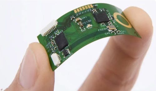
Do you know how much your PCB is warping?
Following the tests conducted on printed circuit boards, it is crucial to understand the deformation values to which the unit was subjected during the test. A "strain gauge" test, which involves using strain gauges, is recommended to ensure certainty regarding these deformations.
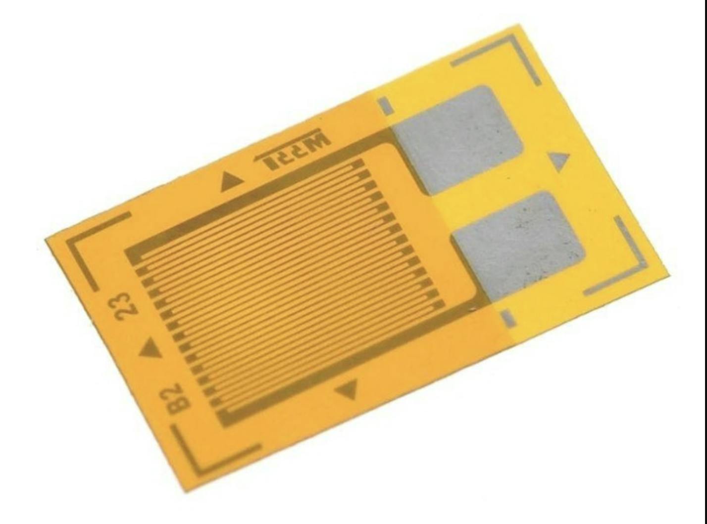
The main component in a strain gauge test is the strain gauge itself, which consists of a thin wire or film that changes its electrical resistance when stretched or compressed. This resistance change can be accurately measured and used to calculate the magnitude of the deformation.
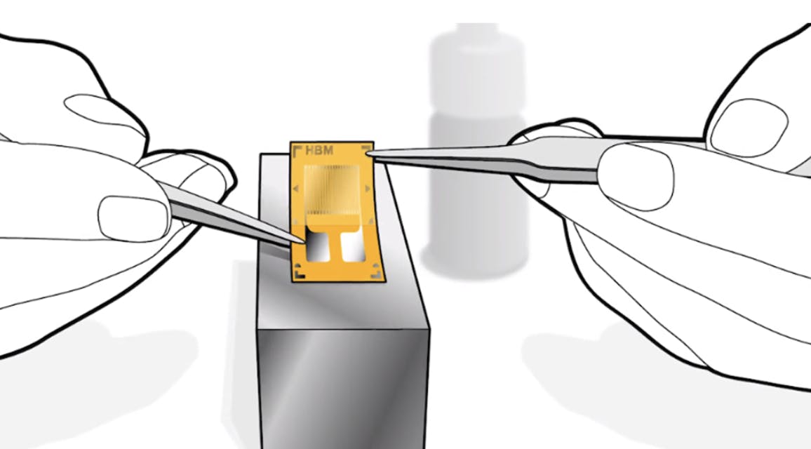
Conducting strain gauge tests begins with cleaning and preparing the area where the strain gauge will be positioned. The strategic placement of the strain gauge is crucial in the test. It is closely related to the type of components present on the PCB and the maximum deformation obtained from a previous finite element analysis (FEA). Next, the sensors are routed and connected to the measuring equipment, ensuring the communication cables are free from any obstruction during the test. The next step is the application of the load, data recording, and analysis.
To address the initial question, I will highlight the importance of conducting strain gauge tests. They are an essential tool in engineering that allows us to understand, measure, and evaluate the structural behavior of a PCB under loads during testing.
Do you have any questions? Feel free to contact us.